Winzo

Made in India app. Click the link to download https://winzo.onelink.me/gu8K/extphbyn
Showing posts with label Material testing. Show all posts

Thursday, March 25, 2021

universal testing machine(UTM)

Testing of materials:

Testing of materials is very important part of the from the point of view of design and manufacturing. It provides the information of material properties, help in ensuring the quality, help in preventing the failures and also helps to make choices among different available materials.

There are mainly two types of testing performed on materials named Mechanical testing and Non-destructive testing. Here, only mechanical testing will be discussed.

Mechanical Testing

Mechanical testing is a destructive type of testing that utilizes static or dynamic forces to reveal the properties of the material. Mechanical testing includes the different types of testing such as Tensile test, hardness testing, impact test, fatigue test, creep test, bend test, etc.

1. Tensile testing:

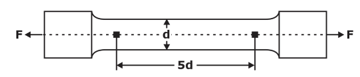
This test is performed on the universal testing machines (UTM). In this test, the specimen is subjected to uniaxial tensile force in a controlled way until its failure. This test helps us in accessing the following properties ductility, yield strength, tensile strength, Young's modulus (E), and Poisson's ratio (μ).

Select the standard specimen and grip it in the crossheads with proper adjustment. While setting up the job, use the adjusting knob to make zero at lower points to zero to remove the dead weight of the lower table. Now, lock the job, fix the extensometer between the gauge length ( to find the extension), and apply the 
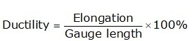
Ductility: It relates the elongation during the tensile test of the material and it is defined as the percentage elongation.
Tensile strength: It is defined as the maximum load per unit cross-section area which the material can bear before breaking. It is given as:

Yield Strength: It is the strength of the material above which permanent deformation takes place in the material under stress.

Young's Modulus (E): It is also known as the modulus of elasticity (E) of the material and it represents the stiffness of the material. It is the measure of the regain of shape and size of the material on the removal of the load.

Compression Test:

A compression test is also carried on the universal testing machine (UTM). Here, the load applied is compressive in  nature and specimen is loaded till it fails. 
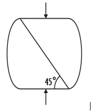
The compression test is generally carried out for the Brittle materials.

2. Hardness Test

Hardness is the surface property of the material which shows the resistance of a material against indentation, penetration and scratching.

Hardness test are as follows:

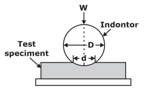
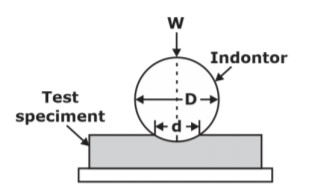
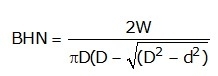
1. Brinell Hardness test: In Brinell hardness test a steel or tungsten carbide ball is used to make a impression in the material under a specified load.
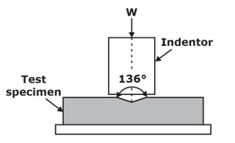
2.Vickers Hardness test: It uses the pyramid indenter of square shape and length of the diagonals of the indentation is measured to calculate the hardness number. It is suitable for very hard and tough materials.

Vickers hardness number is given by:
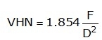
Where F is the applied force (in kg) and D is the average diameter of the diagonals measured.

3. Rockwell Hardness test: Rockwell test sues the diamond cone-shaped or spherical ball type of indenter for the indentation purpose. There are many scales in the Rockwell testing but C scale is the most commonly used scale and hardness on it is denoted as HRC. 

3. Toughness or Impact test

Toughness tests are carried at high strain rates and the energy absorbed by the materials in breaking the specimen is considered the toughness of the material. There are two types of impact tests named Izod and Charpy tests.

Izod test:

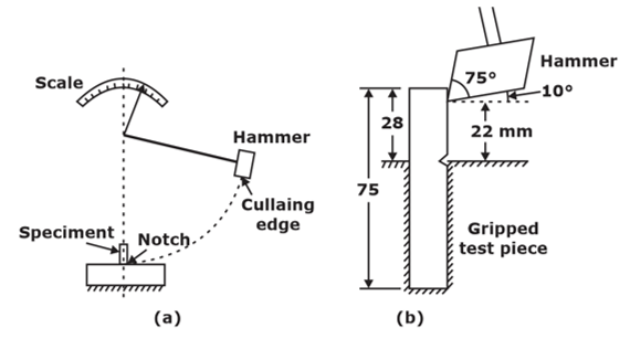
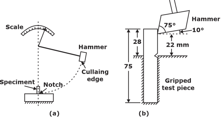
  • For Izod impact testing, the specimen is kept vertically as a cantilever beam. The specimen is kept in such a way that the notch side faces the striking hammer.
 

Charpy test:

The Charpy test shows whether a metal is either brittle or ductile and it is used for predicting ductile to brittle transition.

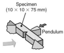
In the Charpy test, the specimen is placed horizontally and fixed at both ends i.e. it is a simply supported beam. Striking hammer strikes from the opposite side of the notch.
4. Flexural or Bending Test

The bend test is a qualitative test that can be used to access the ductility and soundness of a workpiece. Generally, it is used for the butt-welded joints to control their quality.

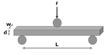
In bend tests, the Rectangular specimen is supported at both ends, and then the load is applied vertically at one or two points. The fracture stress in bending is called as the modulus of rupture, flexural strength.
 

5. Shear Test:

The shear test is used to determine the shear strength of the material which is the maximum shear stress that the material can bear before the appearance of any failure. It plays a key role in the design of fasteners such as bolts and screws.

6. Fatigue Test:

Fatigue is the permanent failure of the material due to fluctuating stresses and failure takes place below the yield point of the metal. The number of cycles at which failure occurs is measured and these can vary from a couple of hundreds to millions of cycles.
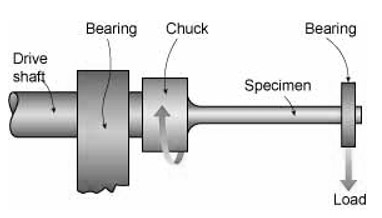
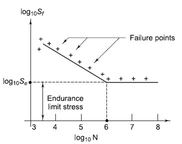
The failure of the specimen under rotating loading is termed fatigue failure. Rotating loading results in completely reversed stresses.

The results of the fatigue test are plotted as an S–N curve which is the graphical representation of stress amplitude and the number of stress cycles (N) before the fatigue failure on a log-log graph paper.

testing of hardness & impact strength

HARDNESS TESTING

Hardness represents the resistance of a material to indentation, penetration and scratching. In hardness testing, a loaded ball or diamond is pressed against the surface of a material which causes the plastic deformation of the same. This deformation is measured by one of the following methods:

(i) Brinell Hardness test-

In this method, a steel hardened ball is pressed into the surface of the material under a specified load. The load is held in position for a fixed period and then released. This leaves a permanent impression in the surface of the material. Then either measure the diameter or the depth of the impression.

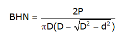
The Brinell specimen Hardness Number (BHN) is defined as the ratio of the applied load to the spherical area of the impression.

Where, P is in Newton.

Conversion tables are also available to determine the hardness number.


(ii) Vicker Pyramid Diamond Method

This method is also similar to the Brinell method except that the indenter is a 136° pyramid diamond on a square base.  As hardness of diamond is excessively high. It can be used for the whole range of materials.

The Vicker Pyramid Number (VPN) is defined as the ratio of applied load to the impressed area. The area is calculated by measuring the length of the diagonal of the square impression on the surface of the material.

(iii) Rockwell Hardness Method –

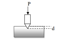
The scale ranges between 0‐100. It uses either a diamond 120° cone indenter or ball indenter made of hardened steel.

Depending on the combination of indenter and load there are several Rockwell hardness scales. Three most commonly used Rockwell hardness scales are given in table.

 The applied load depends on the hardness of material. As a thumb rule the load used for measuring the hardness of steel = 30D2 kg; where D is the diameter of the ball. If D = 10mm the load to be used = 3000kg.

IMPACT TESTING

Static tests are useful only when the loads are static in nature. These tests do not indicate the resistance of a material against shock or impact loads to which usually the automobile parts are subjected to. In such cases, an impact test has to be undertaken. An impact test indicates the toughness of a material which is defined as the energy absorbed by the specimen without fracture.

The following are the main types of impact tests undertaken:

(i) Izod Impact Test

Figure shows an Izod impact testing machine. It consists of an anvil in which a notched specimen can be fixed. The specimen is taken of some standard dimensions. While fixing, care is to be taken to have the notch on the side of the falling hammer and the level with the level of top face of the hammer.

(ii)  Charpy Impact Test

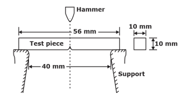
This test is similar to the Izod impact test except that instead of fixing the notched specimen in the anvil, it is supported at each end as a beam as shown in Figure. The hammer strikes at notch in the centre. Impact tests are important as they can reveal the temper brittleness in heat treated materials such as nickel chrome steels.


deflection of beams

The deformation of a beam is usually expressed in terms of its deflection from its original unloaded position. The deflection is measured from the original neutral surface of the beam to the neutral surface of the deformed beam. The configuration assumed by the deformed neutral surface is known as the elastic curve of the beam.

Slope of a Beam: Slope of a beam is the angle between deflected beam to the actual beam at the same point.

Deflection of Beam: Deflection is defined as the vertical displacement of a point on a loaded beam. There are many methods to find out the slope and deflection at a section in a loaded beam.

  • The maximum deflection occurs where the slope is zero.  The position of the maximum deflection is found out by equating the slope equation zero.  Then the value of x is substituted in the deflection equation to calculate the maximum deflection
DIFFERENTIAL EQUATION OF THE DEFLECTION CURVE OF BEAM
Methods of Determining Beam Deflections
Numerous methods are available for the determination of beam deflections. These methods include:
 
Double Integration Method:
  • This is most suitable when concentrated or udl over entire length is acting on the beam.A double integration method is a powerful tool in solving deflection and slope of a beam at any point because we will be able to get the equation of the elastic curve.
  • A double integration method is a powerful tool in solving deflection and slope of a beam at any point because we will be able to get the equation of the elastic curve.
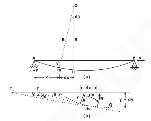
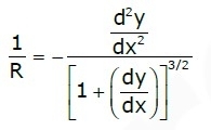
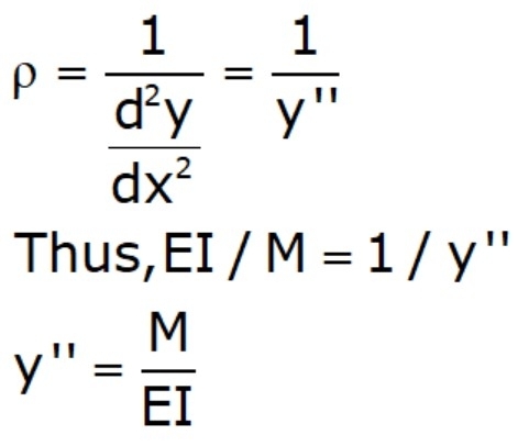
  • In calculus, the radius of curvature of a curve y = f(x) is given by:
  • In the derivation of flexure formula, the radius of curvature of a beam is 
     ρ=EI/M
  • Deflection of beams is so small, such that the slope of the elastic curve dy/dx is very small, and squaring this expression the value becomes practically negligible, hence:
      
  •  If EI is constant, the equation may be written as: 
    EIy′′=M
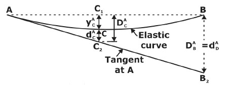
    where x and y are the coordinates shown in the figure of the elastic curve of the beam under load.
  • y is the deflection of the beam at any distance x.
  • E is the modulus of elasticity of the beam,
  • I represent the moment of inertia about the neutral axis, and
  • M represents the bending moment at a distance x from the end of the beam.

The product EI is called the flexural rigidity of the beam.
image001

Integrating one time:

image002 

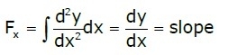
The first integration y'(dy/dx) yields the Slope of the Elastic Curve.
 
Second Integration:
image003
The second integration y gives the Deflection of the Beam at any distance x.
  • The resulting solution must contain two constants of integration since EI y" = M is of second order.
  • These two constants must be evaluated from known conditions concerning the slope deflection at certain points of the beam.
  • For instance, in the case of a simply supported beam with rigid supports, at x = 0 and x = L, the deflection y = 0, and in locating the point of maximum deflection, we simply set the slope of the elastic curve y' to zero

Area Moment Method (Mohr's Method):

  • Another method of determining the slopes and deflections in beams is the area-moment method, which involves the area of the moment diagram.The moment-area method is a
  • The moment-area method is a semi graphical procedure that utilizes the properties of the area under the bending moment diagram. It is the quickest way to compute the deflection at a specific location if the bending moment diagram has a simple shape.

Theorems of Area-Moment Method:
  • Theorem 1
    • The angle  between the tangent of the deflection curve of two points A and B is equal to the negative area of M/EI diagram between the points.
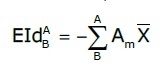
  • Theorem 2
    • The deviation of B from tangent at A is equal to the negative of the statical moment (or the first moment) with respect to B, of the M/EI
      diagram area between A and B.
 Method of Superposition: The method of superposition, in which the applied loading is represented as a series of simple loads for which deflection formulas are available. Then the desired deflection is computed by adding the contributions of the component loads(principle of superposition).
  • Mostly direct formula is used in questions, hence it is advised to look for the beam deflection formula which are directly asked from this topic rather than going for long derivations.

Deflection for Common Loadings:

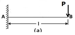
1. Concentrated load at the free end of cantilever beam (origin at A):

  • Maximum Moment, =PL
  • Slope at end: θPL2/2EI
  • Maximum deflection: δ=PL/3EI
  • Deflection Equation (y is positive downward): EIy=(Px2)(3Lx)/6
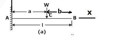
 2 .Concentrated load at any point on the span of cantilever beam
  • Maximum Moment: M= -wa
  • Slope at end: θ=wa2/2EI
  • Maximum deflection: δ = wa3(3La)/6EI
  • Deflection Equation (y is positive downward), 
    • EIy=Px2(3ax)/6 for <
    • EIy=Pa2(3xa)/6 for <L
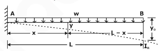
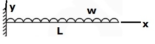
3. Uniformly distributed load over the entire length of cantilever beam
  • Maximum Moment: M=wL2/2
  • Slope at end: θ wL3/6EI
  • Maximum deflection: δ=wL4/8EI
  • Deflection Equation (y is positive downward): EIy=wx2(6L24Lx+x2)/120L
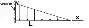
 4. Triangular load, full at the fixed end and zero at the free end
  • Maximum Moment: M=wL2/6
  • Slope at end: θwL3/24EI
  • Maximum deflection, δ=wL4/30EI
  • Deflection Equation (is positive downward): EIy=wx2(10L310L2x+5Lx2x3)/120L
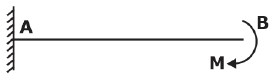
  5. Moment load at the free end of cantilever beam
  • Maximum Moment: M=M
  • Slope at end: θ=ML/EI
  • Maximum deflection: δ=ML2/2EI
  • Deflection Equation (y is positive downward): EIy=Mx2/2

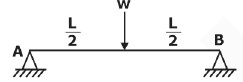
6. Concentrated load at the midspan of simple beam

  • Maximum Moment: M=PL/4
  • Slope at end: θA=θ= WL2/16EI
  • Maximum deflection: δ=PL3/48EI
  • Deflection Equation (y is positive downward): EIy=Px{(3/4)L2x2)}/12 for 0<x<L/2

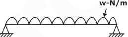
7. Uniformly distributed load over the entire span of simple beam

  • Maximum Moment: M=wL2/8
  • Slope at end: θL=θR=wL3/24EI
  • Maximum deflection: δ 5wL4/384EI
  • Deflection Equation (y is positive downward): EIy=wx(L32Lx2+x3)/24

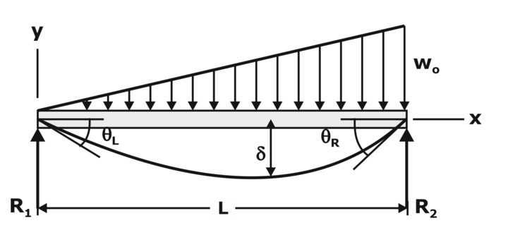
9.Triangle load with zero at one support and full at the other support of simple beam

  • Maximum Moment: M=woL2/9√3
  • Slope at end, 
    • θL7wL3/360EI
    • θR8wL3/360EI
  • Maximum deflection: δ=2.5wL4/384EI at x=0.519L
  • Deflection Equation (is positive downward), EIy=wx(7L410L2x+3x)/360L

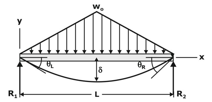
10.  Triangular load with zero at each support and full at the midspan of simple beam

  • Maximum Moment: M=wL2/12
  • Slope at end, θL=θR=5wL3/192EI
  • Maximum deflection: δ=wL4/120EI
  • Deflection Equation (y is positive downward): EIy=wox(25L440L2x2+16x4)/960L      for 0<x<L/2

Conjugate Beam method (Method of elastic weights):

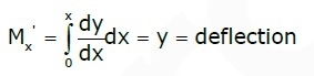
Rule.1: The slope at any point of a real beam, relative to the original axis of the beam, is equal to the shear force at the corresponding point of the conjugate beam.

Rule.2: The deflection at any point of a real beam, relative to the original axis of the beam is equal to the bending moment at the corresponding point of the conjugate beam.

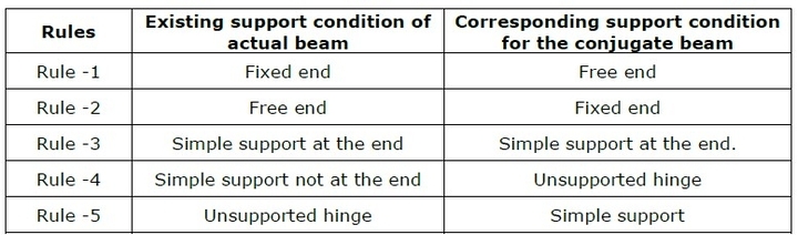
Support conditions for the real and conjugate beam:

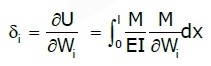
DEFLECTIONS BY CASTIGLIANO'S THEOREM:

Beam Deflection Formula:

  • Cantilever Beams:
f5
  • Simply supported Beams:
f3


What is smartfactory

Smart factories have emerged as the future of manufacturing, revolutionizing industrial processes through advanced technologies and automati...