The joining processes are used to assemble different members to yield the desired complex configuration. Such a complex geometry is either too difficult or impossible to obtain by using only the manufacturing processes. The joining of different elements can be either temporary or permanent in nature. Also, the mechanism of bonding may be either mechanical or atomic. All joining processes involving atomic bonding are of a permanent nature.
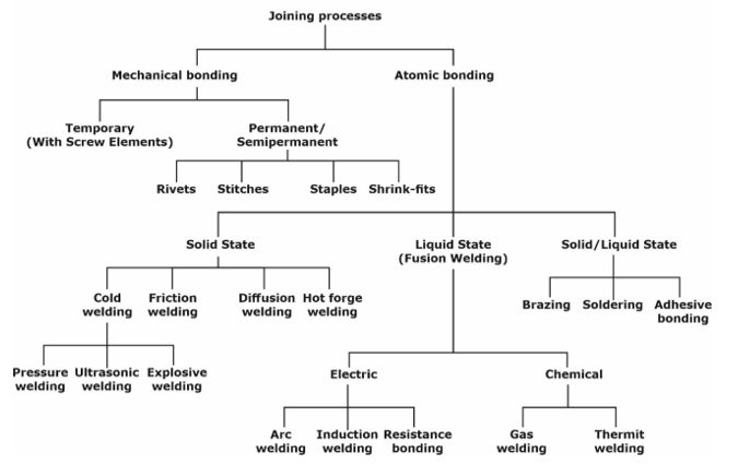 Welding is the process of joining together two pieces of metal so that bonding takes place at their original boundary surfaces”. When two parts to be joined are melted together, heat or pressure or both is applied and with or without added metal for formation of metallic bond.
CLASSIFICATION OF WELDING PROCESSES- BASED ON COMPOSITION
- AUTOGENOUS- In these types no filter material is added during joining. All types of solid phase welding and resistance welding are the examples of this category.
- HOMOGENEOUS- In the homogeneous joining processes, the filler material used to provide the joint is the same as the parent of material. Arc, gas, and thermit welding belong to this category.
- HETEROGENEOUS- In this type a filler material different from the parent material is used. Soldering and brazing are two such joining processes. It may be noted that two materials which are insoluble in each other, such as iron and silver, can be joined by a heterogeneous process. This may be achieved by using a filler material (i.e. copper and tin) which is soluble in both the parent materials (i.e., iron and silver).
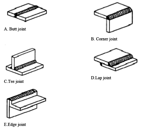
Types of joints- Different types of welding joints are classified as butt, lap, corner, tee and edge joints. Tensile strength of butt joint depends upon the contact area. In case of lap joint, depending upon the strength requirement, the bonding area was chosen. But the limitation of lap joint is that the thickness of joint increases for overlapping of the parts.
WELDING ACCESSORIES
- NON-CONSUMABLE ELECTRODES- They are made of tungsten or carbon. These do not melt in the process of welding and so called non-consumable electrodes. Generally non-consumable electrodes are used in MIG and TIG welding processes.
- COATED CONSUMABLE ELECTRODES- These are the most popular arc welding electrodes. No additional filler metal and flux are required with them. In general, these electrodes have core of mild steel and coating over them of flux material. Coating on the electrode performs many functions. It develops a reducing atmosphere and prevents oxidation, forms separable slag from metal impurities, establishes ac providing necessary alloying elements to the weld pool. Manganese oxide and potassium silicate are the alloying elements and stabilizers.
- WELDING CABLES- Welding cables are required for conduction of current from the power source to various parts of Arc welding process equipment i.e. Electrode, the arc, the workpiece and back to the welding power source. These are insulated copper or aluminium cables.
- HAND SCREEN- Hand screen is used for the protection of eyes during Arc welding process.
- CHIPPING HAMMER- It is used for striking the slag from the weld bead region.
- WIRE BRUSH- A wire brush is generally used to clean the surface before and after the welding process.
- PROTECTIVE CLOTHING- The operator wears protective clothing such as apron to keep away from the exposure of direct heat to the body. Always wear Gloves before touching any item in the workshop.
- Filler Metal- In case of use of non-consumable electrode separate filler metal is used to improve properties of weldment. Selection of a filler metal depends on the metal to be welded. Some common types of filler metal are discussed below.
- COATED FILLER METAL- Rods of this type of filler metal consists the coating of flux material.
- BARE FILLER METAL- No coating of flux is there, it is supplied additionally as per the requirement. For stainless steel and alloy steel filler metal should be alloy of chromium and vanadium. For the welding of copper filler metal should be phosphorous mixed copper. Filler metal composition should be same as that of the material to be welded.
ARC WELDING- Electric arc welding is one of the fusion welding processes in which coalescence of the metal is achieved by the heat from an electric arc between an electrode and workpiece.
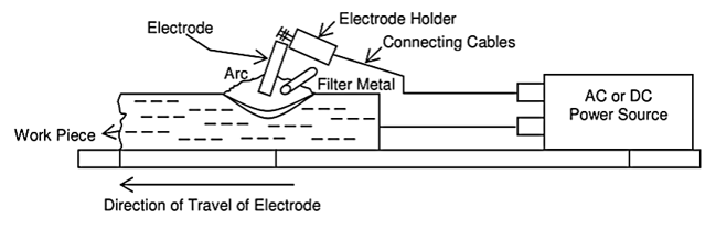
- Electric arc is generated when electrode is brought into contact with the work and is then quickly separated by a short distance approximately 2 mm.
- The circuit operates at low voltage and high current, so arc is established in the gap due to thermionic emission from electrode (Cathode) to workpiece (Anode).
- The arc is sustained due to continuous presence of a thermally ionized column of gas. This arc produces at temperature of the order of 5500°C or higher.
TIG WELDING- In TIG welding process the electrode is non consumable and the purpose of it is only to create an arc. A separate filler metal rod is used to deposit the material. This was primarily invented to weld alloys of Aluminium and Magnesium. Aluminium is very difficult to weld because as soon as it is exposed to atmosphere it forms a layer over it. To weld these materials, work piece should be given negative polarity and electrode positive polarity. As the electrons are coming out of the work piece, peels of the ceramic layer and fresh Aluminium comes in contact with the arc. This phenomenon is called cathodic cleaning.
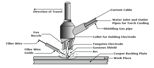
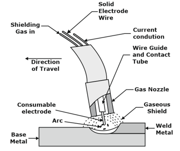
MIG WELDING- MIG works on same principle of TIG or arc welding. It works on basic principle of heat generation due to electric arc. This heat is further used to melt consumable electrode and base plates metal which solidify together and makes a strong joint. The shielded gases are also supplied through nozzle which protect the weld zone from other reactive gases. This gives good surface finish and a stronger joint.
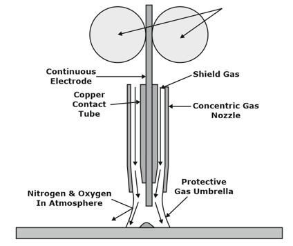 SUBMERGED ARC WELDING (SAW)- This is semi-automatic version of SMAW process which can produce long weld runs. In this type of welding electrode is in the form of spool of copper coated wire and granular flux is used. Copper is coated to increase the conductivity of wire. Powdered flux is initially poured into the welding area and arc is maintained within the pool of flux. This minimizes the Spatter of liquid metal and suppresses the intense ultraviolet radiation Flux is fed on weld zone by gravity through flow nozzle, a long continuous weld can be performed. It is mainly used in the down hand welding position in a semi – automatic welding process and the feeding of electrode towards the weld pool is controlled by machine. The welds obtained by this process are stronger than the base plate, if done carefully.
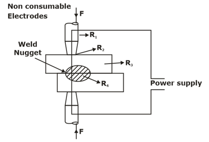
RESISTANCE WELDING- Resistance welding is a fusion pressure welding operation, because of application of large amount of pressure the resistance welding is classified under pressure welding operation. In Resistance welding whatever the heat required for melting and joining of plates is obtained due to electrical resistance circuit, so the name given as resistance welding operation.
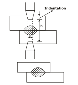
RESISTANCE SPOT WELDING- Resistance spot welding (RSW) is a process in which contacting metal surface points are joined by the heat obtained from resistance to electric current.
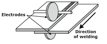
SEAM WELDING- Here the cylindrical electrodes are replaced by disc electrodes. The disc electrodes are continuously rotated so that the workpiece gets advanced underneath them while at the same time the pressure on the joints is maintained. Here the electrodes are not separated at any time.
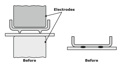
PROJECTION WELDING- The method of joining a projected component on a flat component by using resistance welding is called resistance projection welding. In projection welding, the shape of the electrode remains same as the shape of components to be joined.
OXY-ACETYLENE WELDING (GAS WELDING)- It can used for welding of wide range of metals and alloys. Acetylene mixed with oxygen when burnt under a controlled environment produces large amount of heat giving higher temperature rise. This burning also produces carbon dioxide which helps in preventing oxidation of metals being welded. Highest temperature that can be produced by this welding is 3200.
The chemical reaction involved in burning of acetylene is
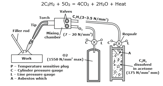
- Oxygen cylinder valves are made of Brass and Acetylene cylinder valves are made by Steel. Brass valve does not corrode so easily and that is why brass valves are used in oxygen cylinder.
- Acetylene is a very dangerous gas because it can explode under its own weight. So, calcium silicate is filled in the cylinder and then acetone is poured. Acetylene is absorbed in acetone.
FLAME FORMATION AND ITS DIFFERENT TYPES- On the basis of supply proportion of acetylene and oxygen, flames can be divided into three categories, neutral flame, carburizing flame and oxidizing flame. These are described here
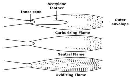
- NEUTRAL FLAME- It produces hissing sound and the flame is used to weld low Carbon steels and Aluminium.
- This consists of nearly one to one ratio of acetylene and oxygen by volume. It consists of two parts namely the inner cone and the outer envelope.
- It has the clear luminous hissing cone indicating that the combustion is complete.
- Such a flame makes the hissing sound and it is useful to weld metals. The temperature of neutral flame is 3150°C.
- CARBURIZING FLAME- It flames contains unburnt Carbon and after solidification of weld the bead will have pitted surface over it and the weld bead appear to be very hard and brittle, because lot of free Carbon will be present in the flame and it is used to weld high Carbon steels and cast Irons.
- It will not produce any sound.
- This flame is obtained when excess of acetylene is supplied than which is theoretically required. It is white in colour due to excess acetylene. The resulting flame will a carburizing flame.
- Its temperature generation range is 3100 C to 3300 C. It is used for the welding of metals where risk of oxidation at elevated temperature is more like aluminium, its alloys and lead and its alloys.
- Oxidizing Flame- Oxidized flames are the hottest flames and it produces roaring sound. This flame has an excess of oxygen over the acetylene.
- It consists of a very short pointed white inner cone and a shorter outer envelope. The reduction of length of the inner cone is a measure of excess oxygen. This is the hottest flame produced.
- These flames are used to weld alloys of Copper and Zinc. In welding these metals, the oxidizing flame produces a base metal oxide layer to protect the evaporation of low point alloying elements. The temperature of these flames is around 3480°C.
Electron Beam Welding- Electron Beam Welding (EBW) is a fusion welding in which coalescence is produced by heating the work piece due to impingement of the concentrated electron beam of high kinetic energy on the work piece.
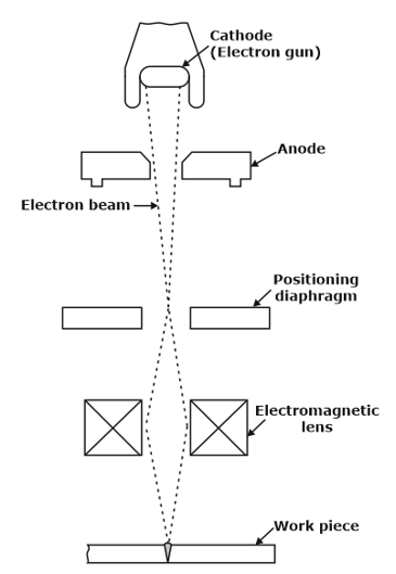
- As the electron beam impinges the workpiece, kinetic energy of the electron beams converts into thermal energy resulting in melting and even evaporation of the work material.
- electron beam welding process is carried out in vacuum. In this process, electrons are emitted from the heated filament called electrode. These electrons are accelerated by applying high potential difference (30 kV to 175 kV) between cathode and anode.
- The electrons get the speed in the range of 50,000 to 200,000 km/s.
- When this high kinetic energy electron beam strikes on the workpiece, high heat is generated on the work piece resulting in melting of the work material.
- Molten metal fills into the gap between parts to be joined and subsequently it gets solidified and forms the weld joint.
Laser Beam Welding- In the LBM process, the laser beam is directed by flat optical elements, such as mirrors and then focused to a small spot (for high power density) at the workpiece using either reflective focusing elements or lenses.
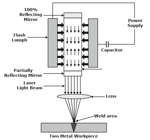
- Inert gas shielding is generally employed to prevent oxidation of the molten puddle and filler metals may be occasionally used.
- The Lasers which are predominantly being used for industrial material processing and welding tasks are the Nd-YAG laser and 1.06 µm wavelength CO2 laser, with the active elements most commonly employed in these two varieties of lasers being the neodymium (Nd) ion and the CO2 molecules respectively.
Gas cutting- For thicker plates and contour ,oxy-fuel cutting is used. The difference in oxyacetylene gas cutting and acetylene welding is a torch tip which is used for preheating the plate as well as providing oxygen jet.
- The tip has a central hole for oxygen jet and surrounded holes for preheating flames.
- When high-pressure oxygen jet with a pressure of order 300kPa is directed against a heated steel plate, the oxygen jet burn the metal and blows it away causing the kerf(cut).
- Larger the size of the orifice, wider is the kerf width and larger is the volume of the oxygen consumed.
Arc cutting- In arc cutting, the metal is simply melted by heat of arc and then blown away by force of arc or by any other gases such as air or shielding gases. Depending upon source of heat input, many arc cuttings are there. In all these processes, the equipment used is similar except the torch. The torch holds the electrode and supply high pressure gas where needed.
- Carbon arc cutting- The process carries a carbon electrode to obtain the required arc. The metal that is cut is blown away by arc force and gravity.
- Air carbon –arc cutting- Here the arc is obtained between copper coated graphite or carbon electrode and the work piece with molten metal being forced out by means of a compressed air at pressure of 550 to 690kPa.
- Oxygen arc cutting- It carries a hollow tubular electrode to obtain the arc. Compressed oxygen is forced through a hollow portion so that metal is oxidized and blown in a similar manner as oxy fuel gas cutting (OFC).
Brazing- Brazing is a coalescence of a joint with the help of a filler metal whose liquidus temperature is above 450o and is below the solidus temperature of the base metal. In brazing, the base metal is not melted. Dissimilar metals can be joined by brazing. Except for aluminum and magnesium, brazing can join almost all metals.
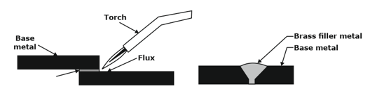
- Brazed joint is not useful for high-temperature welding because of the low melting temperature of the filler metal.
- Here the filler metal reaches the joint by capillary action, it is necessary to control the clearance between two parts. The temperature at which filler metal is entering the joint is also important.
- Too much clearance doesn’t allow the capillary force to draw the filler metal into the joint and also insufficient clearance may be too small to allow the filler metal to give rise to an effective strength.
Soldering- Soldering is the method of joining similar or dissimilar metals by means of a filler metal whose liquidus temperature is below 450o.
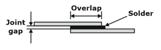
- The joint design used for soldering is similar to that of brazing as in both cases filler metals enter the joint by capillary action.
- Like brazing, soldering also needs solvent cleaning, acid pickling and mechanical cleaning of the joint surface. In order to remove the oxides from the joint surface for avoiding filler metal from oxidizing, fluxes are generally used in soldering.
Weld Defects and Testing- The ideal weld should be such that adequate fusion exists between the filler metal and edge preparation together with good penetration. The major discontinuities are
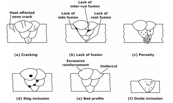
- In welding, the defects often found infusing due to lack of fusion, lack of penetration, inclusion of slag or oxide, presence of cracks, porosity and uncut and excessive penetration.
- These are the defects generally shown in butt welds.
- The defects like cracking, lack of fusion, porosity, slag inclusion, bad profile and oxide inclusion alters the static strength of the welded joint under ductile conditions but have serious consequences if the joint is subjected to fatigue loading.
- The presence of crack enhances the probability of brittle fracture. Similarly a lack of fusion causes a lack of discontinuity and hence diminishes the fatigue strength.


