Winzo

Made in India app. Click the link to download https://winzo.onelink.me/gu8K/extphbyn
Showing posts with label bending moments. Show all posts

Wednesday, March 24, 2021

shear force & bending moments

Beam is defined as a structural member subjected to transverse shear loads during its functionality. Due to those transverse shear loads, beams are subjected to variable shear force and variable bending moment.

Shear force at a cross section of beam is the sum of all the vertical forces either at the left side or at the right side of that cross section.

Bending moment at a cross section of beam is the sum of all the moments either at the left side or at the right side of that cross section.

Types of Rigid Supports

  • Simple Supports
    • Roller Support
    • Hinge Support (or) Pin Support
  • Fixed Supports
    • Clamped Supports (or) Built-in Supports

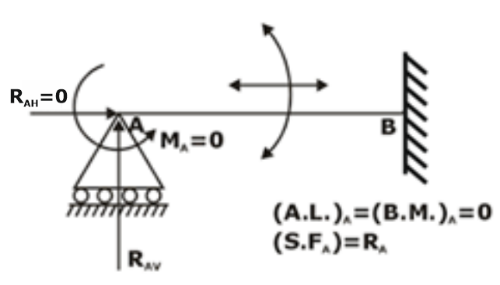
(a) Roller Support – resists vertical forces only
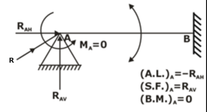
(b) Hinge support or pin connection – resists horizontal and vertical forces
(c) Fixed support or built-in end
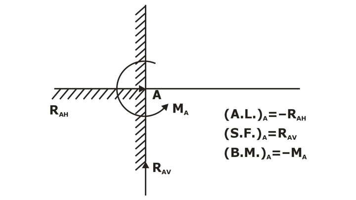
Note: The distance between two supports is known as “span”.

Types of Beams
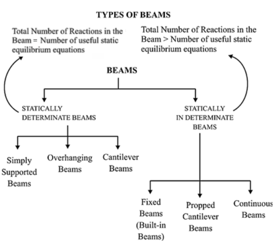
Statically Determinate Beam

A beam is said to be statically determinate if all its reaction components can be calculated by applying three conditions of static equilibrium.

Statically Indeterminate Beam

When the number of unknown reaction components exceeds the static conditions of equilibrium, the beam is said to be statically indeterminate.

(1) Simply supported beam: A beam with two simple supports
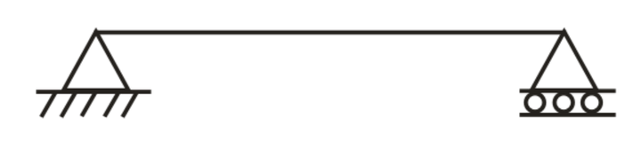
(2) Overhanging beam

(3) Cantilever beam: Beam fixed at one end and free at other
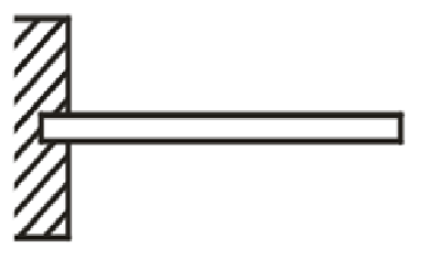
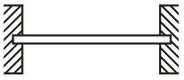
(4) Fixed Beams
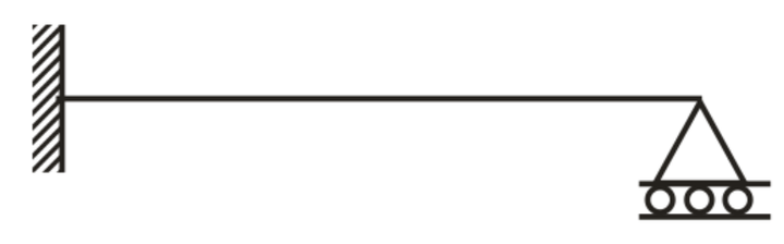
(5) Propped Cantilever Beams
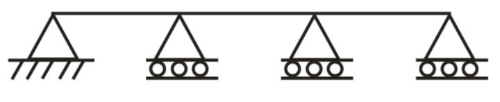
(6) Continuous beam: More than two supports
TYPES OF LOAD

The following are the important types of load acting on a beam,

  1. Concentrated or point load,
  2. Uniformly distributed load, and
  3. Uniformly varying load.

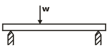
(i) Concentrated or Point Load: load act at a point
 

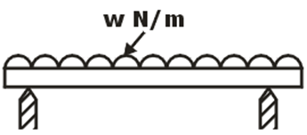
(ii) Uniformly Distributed Load: load spread over a beam, rate of loading w is uniform along the length
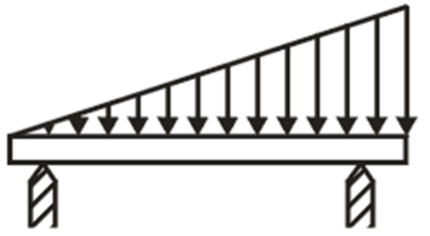
(iii) Uniformly Varying Load: load spread over a beam, rate of loading varies from point to point along the beam
SIGN CONVENTIONS FOR SHEAR FORCE AND BENDING MOMENT

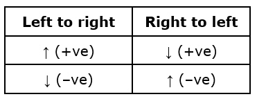
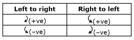
Shear force: If moving from left to right, then take all upward forces as positive and downward as negative.

Or if the shear force tries to rotate the element clockwise then it is takes as positive & if the shear force tries to rotate the element anticlockwise then it is takes as negative.
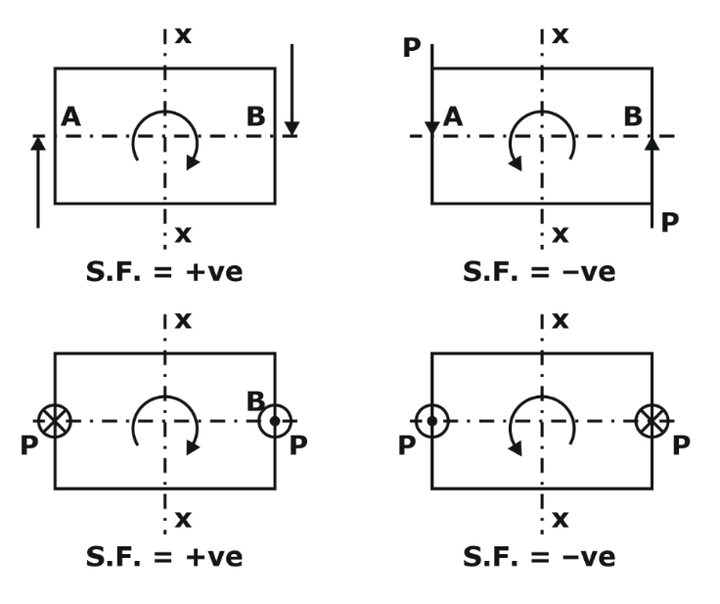
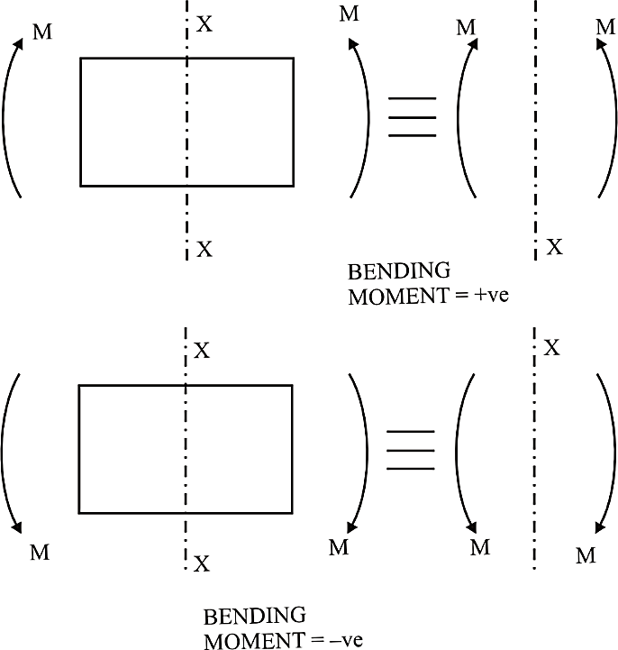
Bending moment: If moving from left to right, take clockwise moment as positive and anticlockwise as negative.

Or if forces are forming sagging moment then it is taken as positive and if forces are forming hogging moment then it is taken as negative.
IMPORTANT POINTS FOR DRAWING SHEAR FORCE AND BENDING MOMENT DIAGRAMS

(i) Consider the left or the right portion of the section.

(ii) The positive values of shear force and bending moments are plotted above the base line, and negative values below the base line.

(iii) The shear force diagram will increase or decrease suddenly i.e., by a vertical straight line at a section where there is a vertical point load.

(iv) The shear force between any two vertical loads will be constant and hence the shear force diagram between two vertical loads will be horizontal.

(v) The bending moment at the two supports of a simply supported beam and at the free end of a cantilever will be zero.
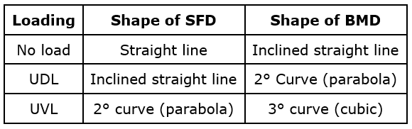
RELATIONS BETWEEN LOAD, SHEAR FORCE AND BENDING MOMENT

A beam is carrying a uniformly distributed load of w per unit length. Consider the equilibrium of the portion of the beam between sections 1-1 and 2-2. This portion is at a distance of x from left support and is of length dx.
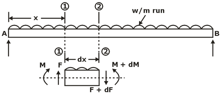
F = Shear force at the section 1-1

F + dF = Shear force at the section 2-2,

M = Bending moment at the section 1-1,

M + dM = Bending moment at the section 2-2.

The forces and moments acting on the length ‘dx’ of the beam are:

  1. The force F acting vertically up at the section 1-1
  2. The force F + dF acting vertically downwards at the section 2-2.
  3. The load w × dx acting downwards
  4. The moments M and (M + dM) acting at section 1-1 and section 2-2 respectively.

The portion of the beam of length dx is in equilibrium. Hence resolving the forces acting on this part vertically, we get

–dF = w.dx
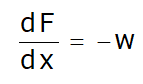
The above equation shows that the rate of change of shear force is equal to the rate of loading.

Taking the moments of the forces and couples about the section 2-2, we get
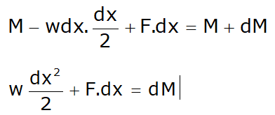
Neglecting the higher powers of small quantities, we get

F.dx = dM
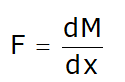
The above equation shows that the rate of change of bending moment is equal to the shear force at the section.


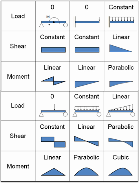
Some Examples:-

Sunday, March 21, 2021

deflection of beams

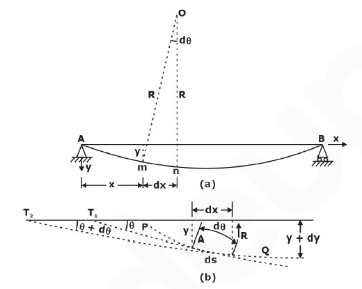
The deformation of a beam is usually expressed in terms of its deflection from its original unloaded position. The deflection is measured from the original neutral surface of the beam to the neutral surface of the deformed beam. The configuration assumed by the deformed neutral surface is known as the elastic curve of the beam.

Slope of a Beam: Slope of a beam is the angle between deflected beam to the actual beam at the same point.

Deflection of Beam: Deflection is defined as the vertical displacement of a point on a loaded beam. There are many methods to find out the slope and deflection at a section in a loaded beam.

  • The maximum deflection occurs where the slope is zero.  The position of the maximum deflection is found out by equating the slope equation zero.  Then the value of x is substituted in the deflection equation to calculate the maximum deflection
DIFFERENTIAL EQUATION OF THE DEFLECTION CURVE OF BEAM
Methods of Determining Beam Deflections
Numerous methods are available for the determination of beam deflections. These methods include:
 
Double Integration Method:
  • This is most suitable when concentrated or udl over entire length is acting on the beam.A double integration method is a powerful tool in solving deflection and slope of a beam at any point because we will be able to get the equation of the elastic curve.
  • A double integration method is a powerful tool in solving deflection and slope of a beam at any point because we will be able to get the equation of the elastic curve.
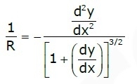
  • In calculus, the radius of curvature of a curve y = f(x) is given by:
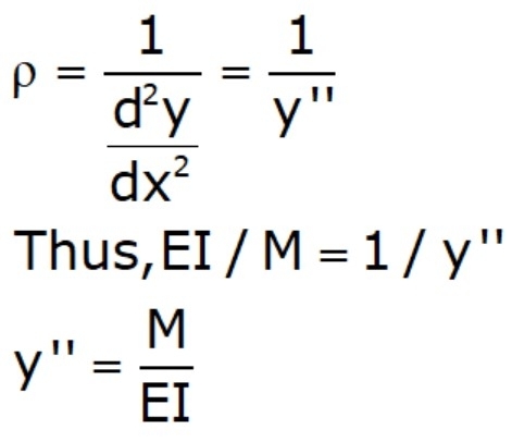
  • In the derivation of flexure formula, the radius of curvature of a beam is 
     ρ=EI/M
  • Deflection of beams is so small, such that the slope of the elastic curve dy/dx is very small, and squaring this expression the value becomes practically negligible, hence:
      
  •  If EI is constant, the equation may be written as: 
    EIy′′=M
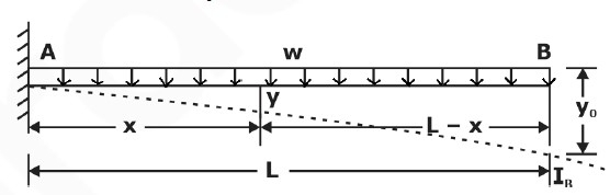
    where x and y are the coordinates shown in the figure of the elastic curve of the beam under load.
  • y is the deflection of the beam at any distance x.
  • E is the modulus of elasticity of the beam,
  • I represent the moment of inertia about the neutral axis, and
  • M represents the bending moment at a distance x from the end of the beam.

The product EI is called the flexural rigidity of the beam.
image001

Integrating one time:

image002 

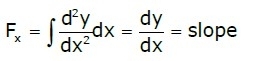
The first integration y'(dy/dx) yields the Slope of the Elastic Curve.
 
Second Integration:
image003
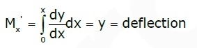
The second integration y gives the Deflection of the Beam at any distance x.
  • The resulting solution must contain two constants of integration since EI y" = M is of second order.
  • These two constants must be evaluated from known conditions concerning the slope deflection at certain points of the beam.
  • For instance, in the case of a simply supported beam with rigid supports, at x = 0 and x = L, the deflection y = 0, and in locating the point of maximum deflection, we simply set the slope of the elastic curve y' to zero

Area Moment Method (Mohr's Method):

  • Another method of determining the slopes and deflections in beams is the area-moment method, which involves the area of the moment diagram.The moment-area method is a
  • The moment-area method is a semi graphical procedure that utilizes the properties of the area under the bending moment diagram. It is the quickest way to compute the deflection at a specific location if the bending moment diagram has a simple shape.

Theorems of Area-Moment Method:
  • Theorem 1
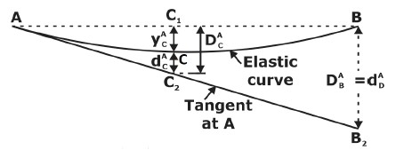
    • The angle  between the tangent of the deflection curve of two points A and B is equal to the negative area of M/EI diagram between the points.
  • Theorem 2
    • The deviation of B from tangent at A is equal to the negative of the statical moment (or the first moment) with respect to B, of the M/EI
      diagram area between A and B.
 Method of Superposition: The method of superposition, in which the applied loading is represented as a series of simple loads for which deflection formulas are available. Then the desired deflection is computed by adding the contributions of the component loads(principle of superposition).
  • Mostly direct formula is used in questions, hence it is advised to look for the beam deflection formula which are directly asked from this topic rather than going for long derivations.

Deflection for Common Loadings:

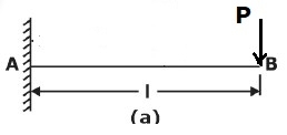
1. Concentrated load at the free end of cantilever beam (origin at A):

  • Maximum Moment, =PL
  • Slope at end: θPL2/2EI
  • Maximum deflection: δ=PL/3EI
  • Deflection Equation (y is positive downward): EIy=(Px2)(3Lx)/6
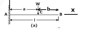
 2 .Concentrated load at any point on the span of cantilever beam
  • Maximum Moment: M= -wa
  • Slope at end: θ=wa2/2EI
  • Maximum deflection: δ = wa3(3La)/6EI
  • Deflection Equation (y is positive downward), 
    • EIy=Px2(3ax)/6 for <
    • EIy=Pa2(3xa)/6 for <L
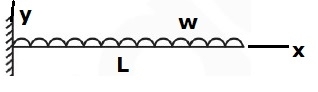
3. Uniformly distributed load over the entire length of cantilever beam
  • Maximum Moment: M=wL2/2
  • Slope at end: θ wL3/6EI
  • Maximum deflection: δ=wL4/8EI
  • Deflection Equation (y is positive downward): EIy=wx2(6L24Lx+x2)/120L
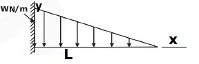
 4. Triangular load, full at the fixed end and zero at the free end
  • Maximum Moment: M=wL2/6
  • Slope at end: θwL3/24EI
  • Maximum deflection, δ=wL4/30EI
  • Deflection Equation (is positive downward): EIy=wx2(10L310L2x+5Lx2x3)/120L
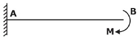
  5. Moment load at the free end of cantilever beam
  • Maximum Moment: M=M
  • Slope at end: θ=ML/EI
  • Maximum deflection: δ=ML2/2EI
  • Deflection Equation (y is positive downward): EIy=Mx2/2

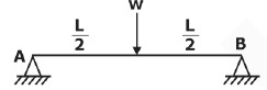
6. Concentrated load at the midspan of simple beam

  • Maximum Moment: M=PL/4
  • Slope at end: θA=θ= WL2/16EI
  • Maximum deflection: δ=PL3/48EI
  • Deflection Equation (y is positive downward): EIy=Px{(3/4)L2x2)}/12 for 0<x<L/2

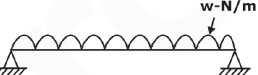
7. Uniformly distributed load over the entire span of simple beam

  • Maximum Moment: M=wL2/8
  • Slope at end: θL=θR=wL3/24EI
  • Maximum deflection: δ 5wL4/384EI
  • Deflection Equation (y is positive downward): EIy=wx(L32Lx2+x3)/24

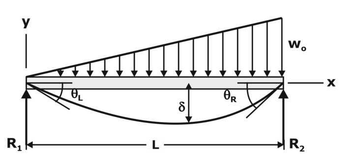
9.Triangle load with zero at one support and full at the other support of simple beam

  • Maximum Moment: M=woL2/9√3
  • Slope at end, 
    • θL7wL3/360EI
    • θR8wL3/360EI
  • Maximum deflection: δ=2.5wL4/384EI at x=0.519L
  • Deflection Equation (is positive downward), EIy=wx(7L410L2x+3x)/360L

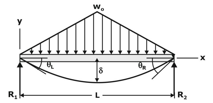
10.  Triangular load with zero at each support and full at the midspan of simple beam

  • Maximum Moment: M=wL2/12
  • Slope at end, θL=θR=5wL3/192EI
  • Maximum deflection: δ=wL4/120EI
  • Deflection Equation (y is positive downward): EIy=wox(25L440L2x2+16x4)/960L      for 0<x<L/2

Conjugate Beam method (Method of elastic weights):

Rule.1: The slope at any point of a real beam, relative to the original axis of the beam, is equal to the shear force at the corresponding point of the conjugate beam.

Rule.2: The deflection at any point of a real beam, relative to the original axis of the beam is equal to the bending moment at the corresponding point of the conjugate beam.

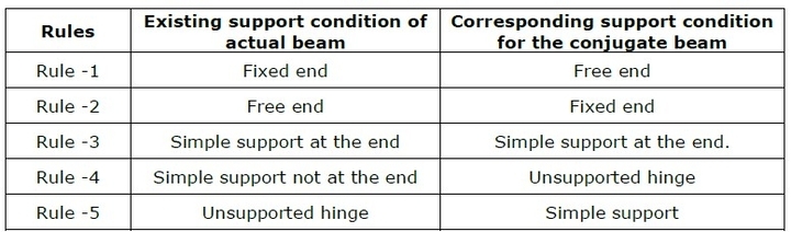
Support conditions for the real and conjugate beam:

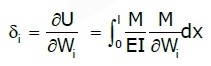
DEFLECTIONS BY CASTIGLIANO'S THEOREM:

Beam Deflection Formula:

  • Cantilever Beams:
f5
  • Simply supported Beams:
f3


What is smartfactory

Smart factories have emerged as the future of manufacturing, revolutionizing industrial processes through advanced technologies and automati...