Hydraulic Turbines and Hydro Machines is the section of Fluid Mechanics which deals with topics such as Turbines, pumps and their working. This section includes all the aspects regarding application of fluid mechanics in the real world.
Hydraulic Machines
- Devices used for the conversion of hydraulic energy into mechanical energy or mechanical energy to hydraulic energy are known as Hydraulic Machines.
- The hydraulic machines which are used for the conversion of hydraulic energy into mechanical energy are known as Turbines and that convert mechanical energy into hydraulic energy is known as Pumps.
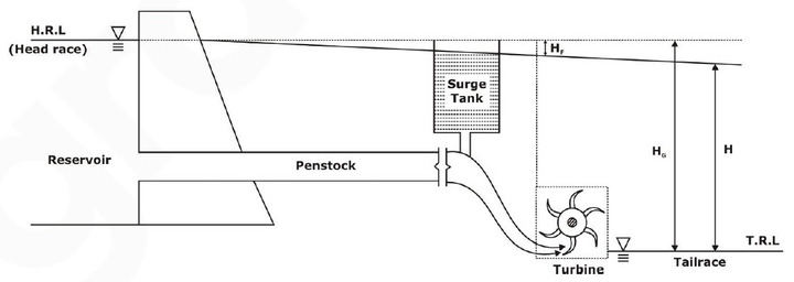
In a Hydroelectric plant as shown above:
- A Dam is constructed across a river or a channel for storing water. The reservoir is also known as Head race.
- Pipes of large diameter called Penstock carry water under pressure from the storage reservoir to the turbines. These pipes are generally made of steel or reinforced concrete.
- Turbines having different types of vanes or buckets or blades mounted on a wheel called a runner.
- Tail-race which is a channel carrying water away from the turbine after the water has worked on the turbines. The water surface in the tail-race is also referred to as tail-race.
Important Terms
- Gross Head (Hg ): Vertical difference between headrace and tailrace.
- Net Head (Hnet): The actual head available at the inlet of the to work on the turbine is called the Net Head.
Hnet = Hg - hL
hL being the total head loss during the transit of water from the headrace to tailrace, mainly the head loss due to friction and is given by: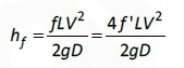
'f' is the coefficient of friction of penstock which depends on the type of material of penstock, 'L' being the total length of the penstock, 'V' the mean flow velocity of water through the penstock, 'D' the diameter of penstock and g is the acceleration due to gravity.
Thus: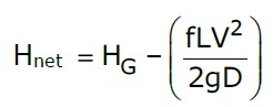
Types of Efficiencies
Considering different forms of input and output, the efficiencies can be classified as:
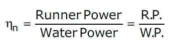
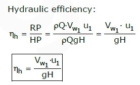
- Hydraulic Efficiency(ηh)
- The ratio of the power generated by the runner of a turbine to the power supplied at the inlet of the turbine is known as Hydraulic efficiency.
- As the power supply is in the hydraulic form, and the possible losses occur between the striking jet and vane, it is rightly called hydraulic efficiency.
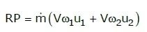
- If R.P. is the Runner Power and W.P. is the Water Power:
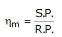
- Mechanical Efficiency(ηm)
- The ratio of the power available at the shaft to the power generated by the runner of a turbine is called Mechanical Efficiency.
- Loss of energy in the runner in the annular area between the nozzle and spear is due to slips and other mechanical problems.
- If S.P . is the Shaft Power:
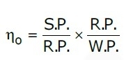
- Overall Efficiency(ηo):
- Ratio of the power available at the shaft to the power supplied to the inlet of a turbine is termed as overall efficiency.
- Because this covers the overall problems of energy losses, it is known as overall efficiency.
- It is dependent on both the hydraulic losses and the slips and other mechanical problems that will create a loss of energy between the jet power supplied and the power produced at the shaft available for coupling of the generator.
- Volumetric Efficiency
![]()
Classification of Turbines
- The hydraulic turbines can be classified on the basis of the type of energy at the inlet, the direction of flow through the vanes, head available at the inlet, discharge through the vanes and specific speed.
- They are classified as:

1. Pelton Turbine
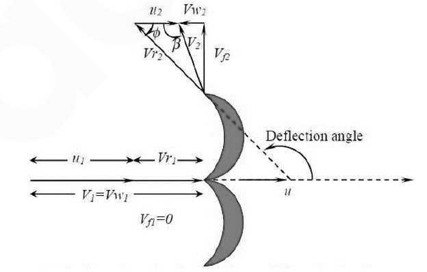
- Pelton wheel turbine is an impulse turbine. In this type of turbine, the nozzle is connected at the exit of penstock which converts the available energy head into velocity head.
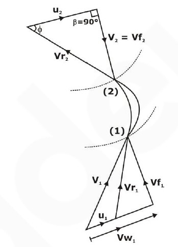
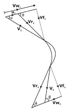
Where:
u= wheel velocity
V= Jet velocity
Vr= relative velocity
Vw=whirl velocity
φ=Angle by the relative velocity at outlet and β= Guide blade angle at the outlet
u1=u2=u=2πN/60 where N= no. of rotation of the wheel
- Tangential flow impulse turbine: Basic components:
(1). Nozzle (2). Runner and buckets (3). Casing (4). Breaking Jet
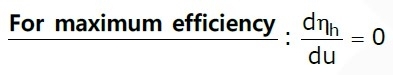
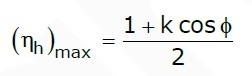
Hydraulic efficiency is given by:
ηh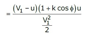
Point to Remember:-
- The velocity of jet: V1=CV×√(2gH) where CV=0.98 to 0.99 and called the coefficient of velocity.
- The velocity of wheel: u=φ √(2gH) where φ = Speed ratio (u/V1) (0.43 to 0.48)
- The velocity of wheel u= πDN (rps)
- Jet ratio (m) =D/d (ratio of pitch diameter to jet diameter; generally 12).
- Number of bucket Z= 15+(D/2d) = 15+0.5 m
- The number of jets is the ratio of total flow rate to the Rate of flow by single jet.
2. Radial Flow Reaction Turbine
- In this type of turbine the water strikes the runner, it has both a kinetic energy head and a pressure energy head. Due to KE head, the impulse will generate, which is similar to in the case of an impulse turbine.
- Impulse: kinetic head
Reaction: Pressure head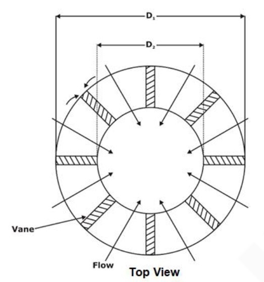
- Let B1, B2 = width of runner at inlet and outlet
Area of flow at inlet: A1 = πD1B1
Area of flow at inlet: A2 = πD2B2
If vane thickness is taken into consideration:
Net Area of flow = [πD1 – nt] · B1 = kπD1B1
K is factor for net area and n is the number of vanes.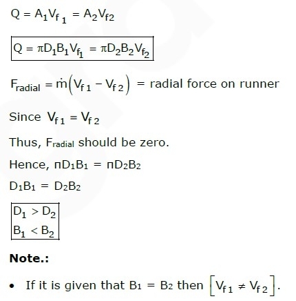
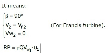
3. Francis Turbine
- Francis turbine is an inward flow reaction turbine.
- To maximize runner power, V2 should be minimum. It can be done by converting absolute velocity direction into radial direction to the runner at exit.
Degree of Reaction (R):
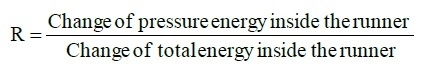
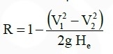 ............ (1)
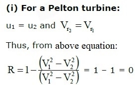
Thus, degree of reaction for the Pelton turbine is zero.
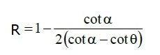
(ii). For Francis turbine:
4. Axial Flow Reaction Turbine
- Kaplan and propeller turbines are examples of axial flow reaction turbines.
Draft Tube
- A draft tube is a pipe of a gradually increasing cross-sectional area, linking the runner outlet to the tailrace and is used to discharge water from the turbine exit to the tail-race.
- An end of the draft tube is linked to the runner outlet and the other end is submerged under the level of water in the tail-race.
Functions:
- It permits a negative head to be established at the outlet of the runner and thereby increasing the NET HEAD on the turbine.
- It converts a large proportion of kinetic energy which was being rejected at the outlet if the turbine into useful pressure energy.
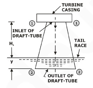
Draft tube efficiency is given by: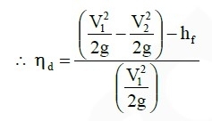
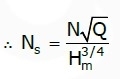
Specific Speed:
- The value of specific speed for a turbine is the speed of a geometrically similar turbine which would produce unit power (one kilowatt) under a unit head (one meter).
- This value is provided by the manufacturer (along with other ratings) and will always refer to the point of maximum efficiency.

- Specific Speed is not a dimensionless number. It dimension [M1/2L-1/4T-5/2].
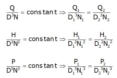
Model Laws:
Centrifugal Pumps
- A hydraulic machine that converts mechanical energy into hydraulic energy or pressure energy is known as a pump.
- A centrifugal pump (also called a Rotodynamic pump or dynamic pressure pump) works on the principle of centrifugal force.
- In Centrifugal pumps, the liquid is subjected to a whirling motion by the rotating impeller which is made of a number of backward curved vanes.
Classification of Centrifugal Pumps:
| S. No. | Classification Criteria | Types of Pumps |
| 1 | Casing design |
|
| 2 | Number of impellers |
|
| 3 | Number of entrances to the Impeller |
|
| 4 | Disposition of shaft |
|
| 5 | Liquid handled |
|
| 6 | Specific speed |
|
| 7 | Head (H) |
|
Heads on a centrifugal pump:
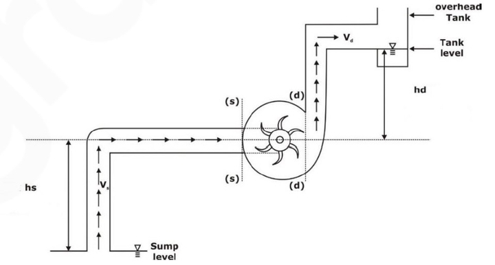
- Suction head (hs)
- It is the vertical distance between the liquid level in the sump and the centre line of the pump.
- It is expressed as meters.
- Delivery head (hd)
- It is the vertical distance between the centre line of the pump and the liquid level in the overhead tank or the supply point.
- It is expressed in meters.
- Static head (Hs)
- It is the vertical difference between the liquid levels In the overhead tank and the sump when the pump is not working.
- It is expressed as meters.
Therefore: Hs= (hs+ hd)
- Friction head (hf)
- It is the sum of the head loss due to the friction in the suction and delivery pipes.
- The friction loss in both the pipes is calculated using the Darcy‟s equation.

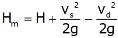
- Total head (H)
- It is the sum of the static head Hs, friction head (hf) and the velocity head in the delivery pipe (V2d /2g). Where, Vd=velocity in the delivery pipe.
- It is the sum of the static head Hs, friction head (hf) and the velocity head in the delivery pipe (V2d /2g). Where, Vd=velocity in the delivery pipe.
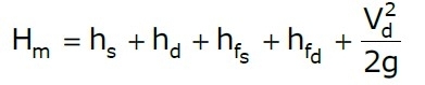
- Manometric head(Hm)
- It is the total head developed by the pump.
- This head is slightly less than the head generated by the impeller due to some losses in the pump.
- Power of pump:
(i). Power requirement of pump = shaft power (SP)
(ii). Impeller power (IP) = SP – (mechanical frictional losses)
(iii). Manometric power or output power (MP)= ρQgHm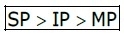
- Efficiencies:
(i). Manometric efficiency (ηm):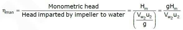
(ii). Mechanical Efficiency: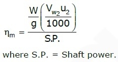
(iii). Overall efficiency: It is defined as ratio of power output of the pump to the power input to the pump. The power output of the pump in kW: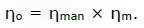
(iv). Volumetric Efficiency: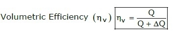
- Specific speed of pump:
Non-dimensional form of specific speed ⇒ It is called the Shape number of pump.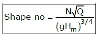
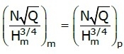
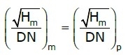
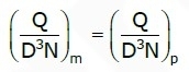
- Model Testing of pumps:
- Priming of centrifugal Pump:
Priming of a centrifugal pump is defined as the operation in which the suction pipe,
casing of the pump and a portion of the delivery pipe up to the delivery valve is completely filled up from outside source with the liquid to be raised by the pump before starting the pump.Thus, the air from these parts of the pump is removed and these parts are filled with the liquid to be pumped.
Minimum starting speed of pump: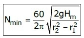
- Cavitation:
(i). Cavitation is defined as the phenomenon of the formation of vapour bubbles of a flowing liquid in a region where the pressure of the liquid falls below its vapour pressure and the sudden collapsing of these vapour bubbles in a region of higher pressure.
(ii). Cavitation results in decrease in turbine efficiency, pitting action, noise, and vibration. - Net Positive Suction Head (NPSH):
(i). The net head developed at the suction port of the pump, in excess of the head due to the vapor pressure of the liquid at the temperature in the pump.
(ii). NPSH must be positive for preventing the liquid from boiling. Boiling or cavitation may damage the pump.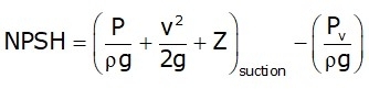
where, Pv is the vapor–pressure of the liquid. If the pump is placed at a height 'z' above the free surface of a liquid where the atmospheric pressure is P. - Multistaging of Pumps:
(i). Pumps in series: The series connection of the pumps is used to increase the total head delivered by the pump.
Q = constant
(ii). Pumps in Parallel: The parallel connection of the pumps is used to increase the total head delivered by the pump.
Hm = constant
Reciprocating pumps:
In the reciprocating pumps, the mechanical energy is converted to hydraulic energy (or pressure energy) by sucking the liquid into a cylinder in which a piston is reciprocating (moving backwards and forward) which exerts the thrust on the fluid and increases the pressure energy.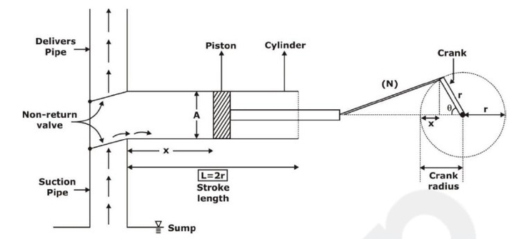 Discharge (Q) is given by:
(i).For Single acting pumps: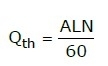
(ii). For double acting pumps: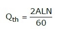
Slip in Reciprocating pumps:
Power in reciprocating pumps: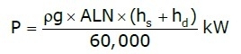
.


No comments:
Post a Comment
Knowing brings controversy