Bending stress and shear stress distribution are classified in the following groups
Bending:
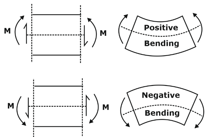
- When the beam is bent by the action of downward transverse loads, the fibres near the top of the beam contract in length whereas the fibres near the bottom of the beam extend.
- Somewhere in between, there will be a plane where the fibres do not change length. This is called the neutral surface. Such a deformation of beam is called the bending.
Bending Moment in Beam:
- Transverse loads or lateral loads: Forces or moments having their vectors perpendicular to the axis of the bar.
- Classification of structural members
- Axially loaded bars: Supports forces having their vectors directed along the axis of the bar.
- Bar in tension: Supports torques having their moment vectors directed along the axis.
- Beams
- Subjected to lateral loads.
- Beams undergo bending (flexure) because of lateral loads.
When the beam is subjected to a bending moment or bent there are induced longitudinal or bending stress in cross-section.
Bending Stress in beam

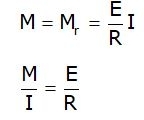
- I is Moment of Inertia about Neutral Axis.
- Note that a positive bending moment M causes negative (compressive) stress above the neutral axis and positive ( tensile) stress below the neutral axis
Equation of Pure Bending

Assumptions:
- The material of the beam is homogeneous and isotropic.
- The value of Young's Modulus of Elasticity is same in tension and compression.
- The transverse sections which were plane before bending, remain plane after bending also.
- The beam is initially straight and all longitudinal filaments bend into circular arcs with a common centre of curvature.
- The radius of curvature is large as compared to the dimensions of the cross-section.
- Each layer of the beam is free to expand or contract, independently of the layer, above or below it.
Modulus of Section
Elastic section modulus is defined as Z = I / y, where I is the second moment of area (or Izz moment of inertia) and y is the distance from the neutral axis to any given fibre.
- Section modulus is a geometric property for a given cross-section used in the design of beams or flexural members.
- For the equilibrium of the section, the moment of resistance must be equal to the bending moment M. Hence:
- Rectangular section:
![]()
- Modulus of the section :

- Circular section:
![]()
- Modulus of section :
![]()
Beams of uniform strength
- The beam is said to be in uniform strength if the maximum bending stress is constant across the varying section along its length.
- Generally, beams are having the uniform cross-section throughout their length. When a beam is loaded, there is a variation in bending moment from section to section along the length. The stress in extreme outer fibre (top and bottom) also varies from section to section along their length. The extreme fibres can be loaded to the maximum capacity of permissible stress (say σmax), but they are loaded to less capacity. Hence, in beams of uniform cross section, there is a considerable waste of materials
- When a beam is suitably designed such that the extreme fibres are loaded to the maximum permissible stress σmax by varying the cross-section it will be known as a beam of uniform strength
Shearing Stress
In the theory of bending, presence of shear and the distortion of plane sections was neglected because the effect of it is not on bending stress is not of practical importance.
- But, it is important to consider the shear stresses for their own importance.
- Here, only the shearing stresses in the transverse palnes parallel to the shearing force and the complimentary shear stresses in the longitudinal planes parallel to the axis of the beam.
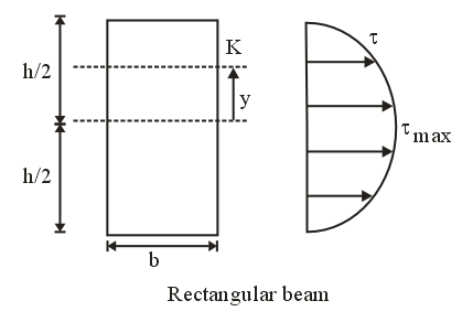
Shear stress distribution over rectangular section
Fig. shows the rectangular cross-section of the beam, over which we have to determine the distribution of shear stress. Consider a layer ab at any above the N.A.
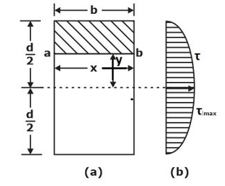
Shearing stress on a layer JK of beam at distance y from neutral axis.
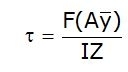

Where,
- V = Shearing force
 First moment of area
![]()
Shear stress in Rectangular Beam
- Suppose, we have to determine the shear stress at the longitudinal layer having y distance from neutral axis.


Circular Beam
- Centre of gravity of semi-circle lies at distance from centre or base line. As it is symmetrical above neutral axis, hence at neutral axis shear stress will be maximum.

![]()
![]()

Shears Stress in Hollow Circular Cross-Section
- In hollow circular cross-section, if we have to calculate τ at neutral axis by the formula

Shear Stress in Triangular Section
- In a triangular cross-section, if we have to calculate τ at neutral axis, then in formula

![]()
Shear Stress in I-section


Combined Stresses
Under combination of
- Direct Stress
σd= P/A
where P = axial thrust, A = area of cross-section
- Bending Stress
σb= My/l
where M = bending moment, y- distance of fibre from neutral axis, I = moment of inertia.
- Shear stresses
Τ= Tr/J
where T = torque, r = radius of shaft, J = polar moment of inertia.
Combined Stress is:
Equivalent Torsional Moment:-
The equivalent torsional moment is defined as the torsional moment, which when acting alone, will produce the same torsional shear stress
in the shaft as under the combined action of bending moment (Mb) and torsional moment (Mt)
![]()
Equivalent Bending Moment:-
The equivalent Bending moment is defined as the bending moment, which when acting alone, will produce the same bending stresses (tensile and compressive) in the shaft
as under the combined action of bending moment (Mb) and torsional moment (Mt)
![]()
Example:- A shaft of diameter 8 cm is subjected to a bending moment of 3000 Nm and a twisting moment of 4000 Nm. The maximum normal stress induced in the shaft is equal to
Solution:-

Stress due to combined direct and bending load:
Suppose a beam under direct compressive and bending load as shown in the diagram. where A=Area,
y=distance of extreme fiber from Neutral axis and I= moment of Inertia
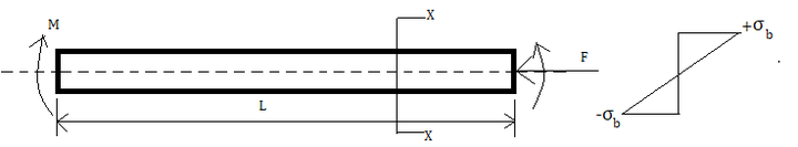

so, total stress at upper fibre = Direct compressive stress+ tensile stress due to a bending load
=(-σ)+σb
= ![]()
Same for lower extreme fiber= Direct compressive stress+ Compressive stress due to bending load
=(-σ)+(-σb)
=![]()
Example-
- For the component loaded with a force F as shown in the figure, the axial stress at the corner point P is

Solution:-
- At point P two types of stress are acting, bending & axial tensile load
- So, bending stress =

Axial tensile stress =
Total axial stress at P = σb + σa


No comments:
Post a Comment
Knowing brings controversy