INTRODUCTION
An engine is a device which transforms one form of energy into another form. Normally, most of the engines convert thermal energy into mechanical work and therefore they are called 'heat engines'.
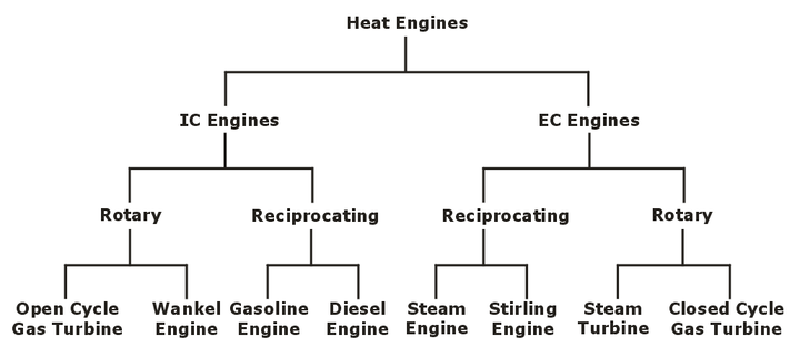
Heat engines can be broadly classified into two categories:
(i) Internal Combustion Engines (IC Engines)
(ii) External Combustion Engines (EC Engines)
CLASSIFICATION OF HEAT ENGINE
Engines whether Internal Combustion or External Combustion can be classified into two types,
(i) Rotary engines
(ii) Reciprocating engines
BASIC ENGINE COMPONENTS
An engine is made up of by combining several components out of which some important components are discussed below.
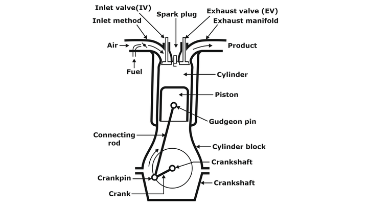
NOMENCLATURE
(i) Cylinder Bore(d)
The nominal inner diameter of the working cylinder is called the cylinder bore and is designated by ‘d’.
(ii) Piston Area (A)
The cross-sectional area of cylinder is called the piston area and is designated by ‘A’.
![]()
(iii) Stroke (L)
The nominal distance through which a working piston moves between two successive reversals of its direction of motion is called the stroke.
(iv) Dead Centre
The position of the working piston at the moment when the direction of the piston motion is reversed at either end of the stroke is called the dead centre. There are two dead centres in the engine
(a) Top Dead Centre
(b) Bottom Dead Centre
(a) Top Dead Centre (TDC): Dead centre when the piston is farthest from the crankshaft or nearest to cylinder head is known as Top Dead centre.
(b) Bottom Dead Centre (BDC): Dead centre when the piston is nearest to the crankshaft or farthest from the cylinder head is known as Bottom dead centre.
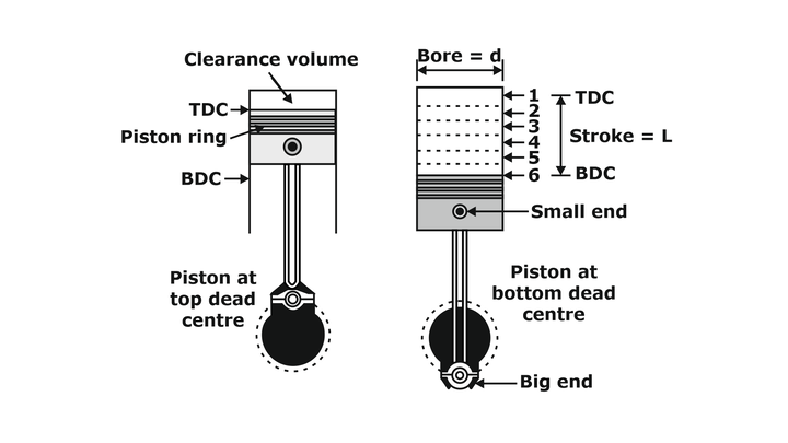
Fig.: Nomanclature of an Internal Combustion Engine
(v) Displacement or Swept Volume (Vs)
The volume swept by the piston when travelling between both dead centers is called the displacement volume.
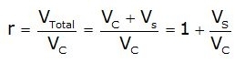
(vi) Compression Ratio (r)
It is the ratio of the total cylinder volume when the piston is at the bottom dead centre, VTotal, to the clearance volume, Vc.
The three cycles of great practical importance in the analysis of piston engine performance are
(i) Constant Volume or Otto Cycle
(ii) Constant Pressure or Diesel Cycle
(iii) Dual Combustion or Limited pressure Cycle.
Constant Volume or Otto Cycle
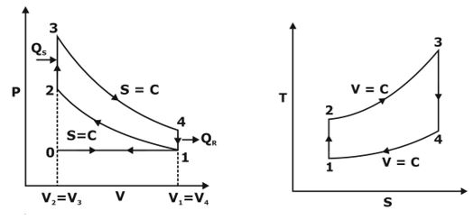
Fig.: P-V & T-S diagram of otto Cycle
Working of otto cycle –
When the engine is working on full throttle, the processes 0→1 and 1→0 on the p-V diagram represents suction and exhaust processes and their effect is nullified.
Process 1→2 represents isentropic compression of the air when the piston moves from bottom dead centre to top dead centre and charge (mixture of fuel and air) is compressed to a higher pressure.
Process 2→3 heat is supplied reversibly at constant volume.
This process corresponds to spark-ignition and combustion in the actual engine starts.
Processes 3→4 represent isentropic expansion where the product of expands & piston moves from top dead centre to bottom centre.
Process4→1 represent constant volume heat rejection in which piston is stays at bottom dead centre.
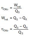
Thermal Efficiency
The thermal efficiency of Otto cycle can be written as,
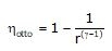
From the above expression we can see that thermal efficiency of Otto cycle is a function of compression ratio r and the ratio of specific heats γ.
Further, the efficiency is independent of heat supplied and pressure ratio.
The use of gases with higher γ values would increase efficiency of Otto cycle.
Shows the effect of γ and r on the efficiency.
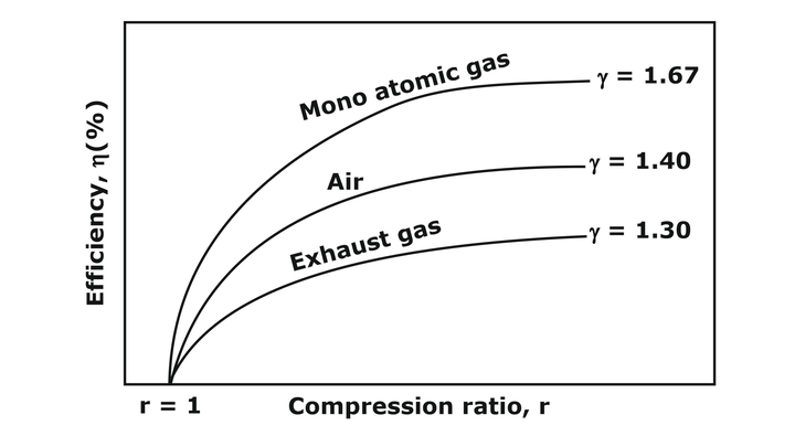
Fig.: variation of efficiency with specific heat ratio
Work Output
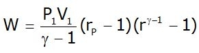
Thus, it can be seen that the work output is directly proportional to pressure ratio, rp.
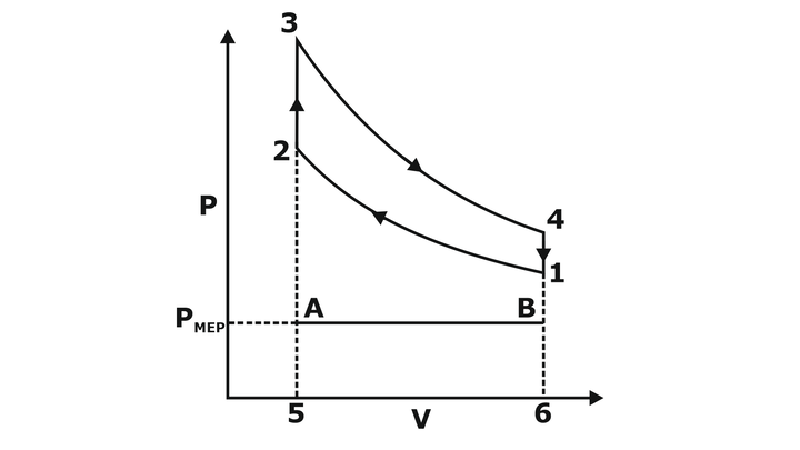
Fig.: Mean Effective Pressure
The mean effective pressure of the cycle is given by,
![]()
The mean effective pressure which is an indication of the work output increases with a pressure ratio at a fixed value of compression ratio and ratio of specific heats.
CONSTANT PRESSURE OR DIESEL CYCLE:
Process 1→2 represents isentropic compression of the air when the piston moves from bottom dead centre to top dead centre and air is compressed to a higher pressure.
Process 2→3 heat is supplied reversibly at constant pressure.
This process corresponds to injection of fuel through fuel injector and combustion due to self-ignition of fuel
Processes 3→4 represent isentropic expansion where the product of expands & piston moves from top dead centre to bottom centre.
Process4→1 represent constant volume heat rejection in which piston is stays at bottom dead centre.
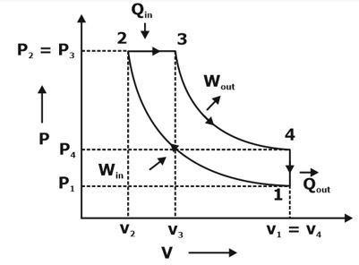
Fig.: P-V & T-S diagram of Diesel cycle
The difference between Otto and Diesel cycles is in the process of heat addition.
In Otto cycle the heat addition takes place at constant volume whereas in the Diesel cycle it is at constant pressure.
For this reason, the Diesel cycle is often referred to as the constant-pressure cycle.
Thermal Efficiency
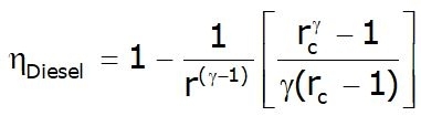
From the above expression, we can see that the efficiency of the Diesel cycle is different from that of the Otto cycle only in the bracketed factor.
This factor is always greater than unity. Hence for a given compression ratio. the Otto cycle is more efficient.
In diesel engines the fuel cut-off ratio, rc, depends on output, for maximum output rc maximum.
Therefore, unlike the Otto cycle the air-standard efficiency of the Diesel cycle depends on output.
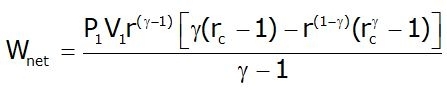
Work Output:
The net work output for a Diesel cycle is given by,
Mean effective pressure
The mean effective pressure of the cycle is given by,
![]()
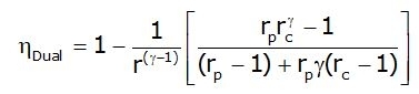
DUAL COMBUSTION OR MIXED OR LIMITED PRESSURE CYCLE
The name dual combustion is derived from the fact that it incorporates into it the features of both Otto and Diesel cycles.
Heat addition at constant volume tends to increase the efficiency of the cycle whereas switching over to constant pressure heat addition limits the maximum pressure.
Hence, this cycle is also called limited pressure cycle.
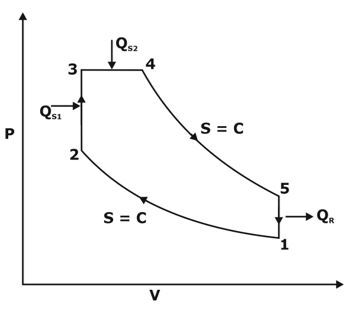
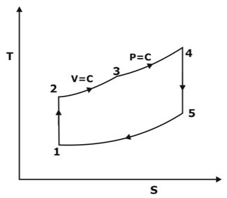
Fig.: P-V & T-S diagram of Dual cycle
COMPARISON OF OTTO, DIESEL, AND DUAL CYCLES
In order to compare the performance of the Otto, Diesel and Dual combustion cycles some of the variable factors must be fixed.
(i) For same compression ratio and same heat addition:
![]()
(ii) Same Compression Ratio and Heat Rejection:
![]()
(iii) Same Peak Pressure, Peak Temperature and Heat Rejection:
![]()
(iv) Same Maximum Pressure and Heat Input:
![]()
(v) For same maximum pressure and work output:
![]()
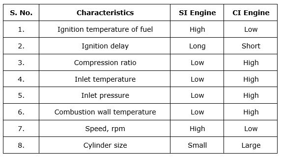
Variables Affecting Knock in an SI & CI Engine:
ENGINE POWER
The energy flow through the engine is expressed in three distinct terms.
They are indicated power, IP, friction power FP and brake power, BP.
Indicated power can be computed from the measurement of forces in the cylinder and brake power may be computed from the measurement of forces at the crankshaft of the engine. The friction power can be estimated by motoring the engine or other methods.
It can also be calculated as the difference between the IP and BP if these two are known, then,
IP = BP +FP
FP = IP – BP
Indicated Mean Effective Pressure (Pim)
It is a mean value expressed in N/m2, which, when multiplied by the displacement volume, Vs,
Gives the same indicated net work as is actually produced with the varying pressures.
![]()
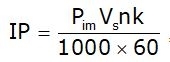
Where IP = indicated power (kW)
Pim = indicated mean effective pressure (N/m2)
L= length of the stroke (m)
A = area of the piston (m2)
N = speed in revolutions per minute,
n = number of power strokes per minute= N/2 for a four-stroke engine N for a two-stroke engine
K =number of cylinders
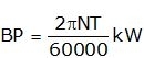
Brake Power (BP)
This power is interchangeably referred to as brake power, Shaft power or delivered power'.
In general, only the term brake power, bp, has been used in this book to indicate the power actually delivered by the engine.
ENGINE EFFICIENCIES:
Apart from expressing engine performance in terms of power, it is also essential to express in terms of efficiencies.
AIR-STANDARD EFFICIENCY:
The air-standard efficiency is also known as thermodynamic efficient mainly a function of compression ratio and other parameters.
INDICATED AND BRAKE THERMAL EFFICIENCIES:
The indicated and brake thermal efficiencies are based on the ip and bp of the engine respectively.
MECHANICAL EFFICIENCY:
The mechanical efficiency, ⴄm of the engine can be expressed as the ratio of bmep to imep.
Mechanical efficiency takes into account the mechanical losses in an engine.
Mechanical in general, mechanical efficiency of engines varies from 65 to 85%.
RELATIVE EFFICIENCY:
The relative efficiency or efficiency ratio as it is sometimes called is the ratio of the actual efficiency obtained from an engine to the theoretical efficiency of the engine cycle
![]()
VOLUMETRIC EFFICIENCY:
Volumetric efficiency is defined as the ratio of the actual mass of air drawn in to the engine during a given period of time to the theoretical mass which should have been drawn in during that same period of time, based upon the total piston displacement of the engine, and the temperature and pressure of the surrounding atmosphere.
![]()


No comments:
Post a Comment
Knowing brings controversy